Helical Gear mold
| Information | |
| Industry | Grinders, blenders, automatic curtain motors, lifting clothes rack drives;
Paper feed transmission for printers & scanners |
| Product | Helical Gear |
| Challenges | High precision tolerance and Concentricity |
| Technology | Injection mold |
| Surface Finish | SPI B1 |
| Material | POM |
| Cavities | 1*8 |
| Mold size | 300X270X400 mm |
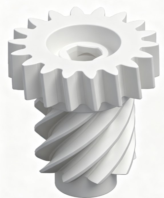
Products Introduction
1,Upper Section: Helical Gear Segment
- External helical tooth design features high contact ratio, low running noise and superior load capacity compared to spur gears.
- Central special-shaped bore with square keyway for torque transmission and anti-rotation positioning with the drive shaft.
- Flat gear end face allows installation of gaskets to limit axial displacement.
2, Middle & Lower Section: Single-Start Worm Segment
- Single-start worm with small lead angle, paired with a worm wheel to achieve 90° cross-axis power conversion and large reduction ratio.
- Cylindrical journal reserved at the bottom for bearing assembly to support overall rotational movement.
3, Overall Characteristics
The helical gear and worm are integrally formed as a single component with no assembly clearance, delivering higher transmission precision and fewer individual parts. It is commonly manufactured via plastic injection molding,
DFM Analysis
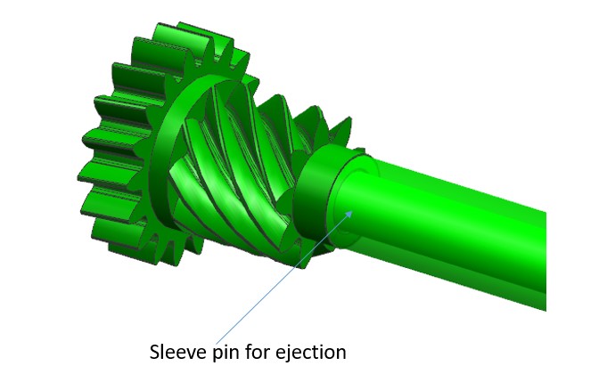
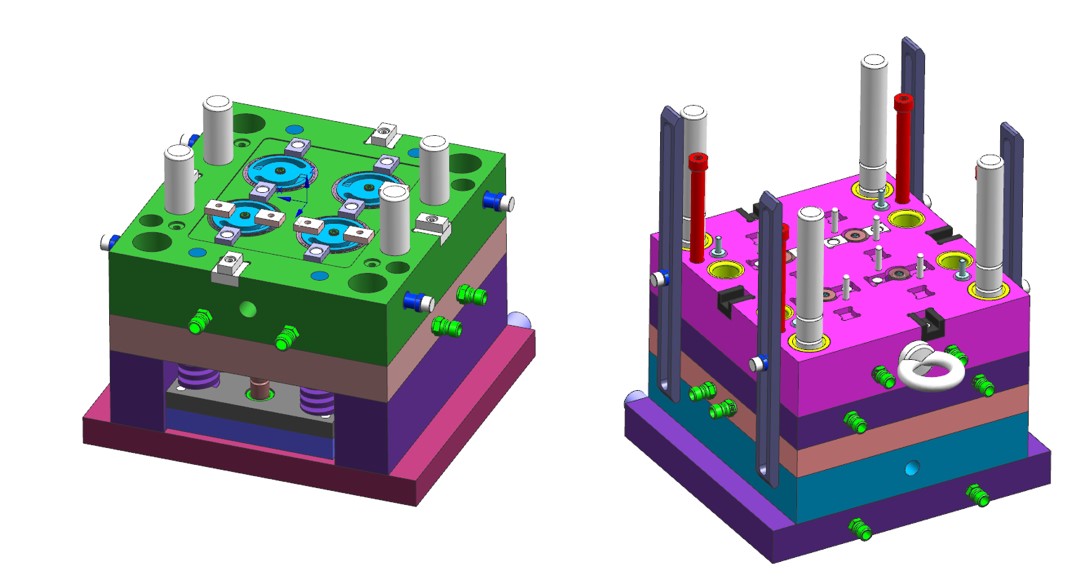
Mold design
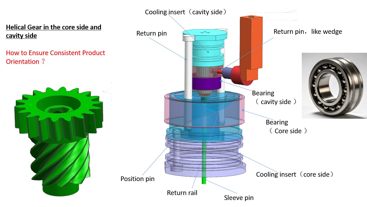
Key point on the mold
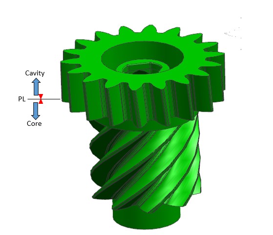
Both the cavity side and core side have helical teeth, and the part also has irregular contours. The key difficulty is ensuring uniform molded parts in every injection cycle. We need to securely lock the rotational position of the rotating inserts. Bearings only allow free rotation and cannot fix the angular position reliably.
Therefore, we have designed wedge locks on the cavity side and return pins on the core side. This mechanism accurately returns the part to its original position after each rotation, so consistent part features can be maintained for every injection molding cycle.
- Precise Angle Matching Requirement
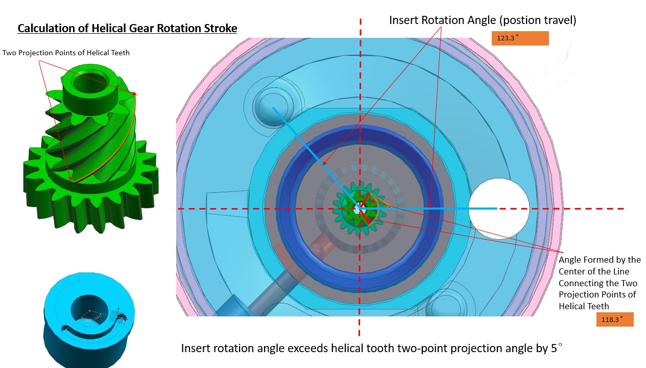
The insert rotation angle, helical tooth lead, and axial core-pulling travel must be perfectly linked. If there is an angular deviation (such as the 2° tolerance you mentioned earlier) between the insert rotation angle and the two-point projection angle of the helical teeth, it will directly cause scratching, dragging, or chipping of the gear teeth.
Unlike straight threads which only require linear core pulling, helical teeth perform a compound spiral motion: axial retraction synchronized with rotation. The tolerance for matching rotation angle, travel and helix angle is extremely low.
- High Sensitivity to Clearance of Synchronization Mechanisms
Drives using oil cylinders or racks & pinions to rotate inserts feature gears and bearings. Tiny clearances will lead to rotational lag and tooth surface interference during demolding; overly tight clearances will result in jamming or burnt bearings.
- Challenges in Controlling Helical Tooth Form Accuracy
- Consistency of Helix Angle
The helix angle directly determines the meshing precision of finished gears. Minor angular errors during CNC or EDM machining of spiral insert surfaces will lead to jamming and abnormal noise during assembly. Polishing may easily alter the helix gradient, which does not occur with straight teeth.
- Tooth Deformation Caused by Uneven Shrinkage
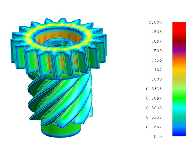
Plastic cools and shrinks unevenly along the spiral direction, causing deviations in tooth thickness and helix angle. Thick-walled gears are prone to tooth direction warpage and excessive meshing clearance.
- Uneven Demolding Stress on Fine Helical Teeth
Helical teeth bear unilateral force during ejection, creating concentrated stress at the tooth root. Thin-tooth and small-module gears are highly susceptible to whitening or fracture during demolding.
- Complex Mold Structure & Limited Internal Space
- Rotational Core-Pulling Mechanism Occupies Large Mold Space
Components including rotating inserts, thrust bearings, guides, rack-and-pinion transmission, travel limit blocks and anti-rotation pins must be arranged inside the mold. Compared with standard straight core-pulling molds, a much larger mold base is required, and component interference frequently occurs.
- Strict Requirements for Limiting & Anti-Mistake Design
Accurate rotation angle limiting is mandatory (corresponding to the angular tolerance control mentioned previously). Over-rotation will collide and damage gear inserts; insufficient rotation prevents smooth core pulling. Dual protection consisting of mechanical limit blocks and position sensors is required, further complicating the structure.
- Difficult Stress Balancing
Single sets of rotating inserts bear unilateral demolding force. For multi-cavity molds, synchronous movement of all rotational assemblies must be guaranteed, otherwise uneven ejection and flash will occur.
Summary
The part may seem simple, but strict requirements for appearance and assembly demand extremely high mold machining precision. We adopt imported DMG CNC machines, Sodick EDM and wire cutters for production, keeping machining tolerance within 0.02 mm.
All components undergo full inspection via CMM after processing to eliminate defects at the early stage and minimize issues during subsequent mold trials. The customer attended the trial run and highly praised our solution of adding 3D-printed cooling inserts to resolve product deformation. Despite the higher costs, the final trial results fully satisfied the client.