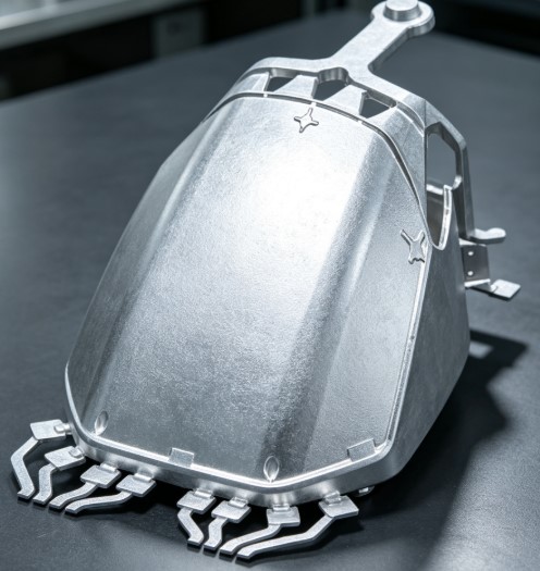
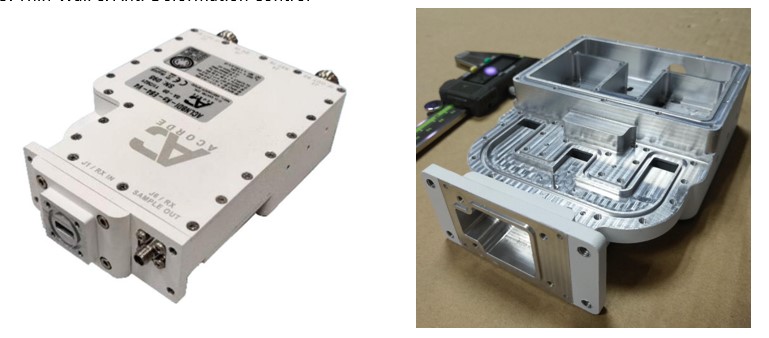
Aluminum 6082 -T6 Military Professional Satellite Communication Terminal housing part
Products Introduction
| Information | |
| Industry | Military / Professional Satellite Communication Terminal |
| Product | Communication device housing |
| Challenges | Precise assembly surfaces, Over 100 screw holes,White Coating |
| Technology | CNC machining |
| Surface Finish | 650 Passivation Trivalent Chromate and powder white coating |
| Material | Aluminum 6082 -T6 |
| Quantity | 25 pcs |
| Lead Time | 15 Business days |
Communication housing products require high precision, low deformation, excellent electrical & thermal conductivity, strict surface treatment and strong EMC shielding performance, to ensure stable signal transmission, reliable heat dissipation and long-term weather resistance.
- Key Properties: High electrical conductivity (≥28 MS/m for EMI shielding); low residual stress; uniform grain structure (≥ASTM Grade 8); thermal expansion coefficient matched with PCB (≈23 ppm/℃).
- Dimensional & Geometric Tolerance (Core)
Dimensional Tolerance: General ±0.05 mm; 5G/mmWave cavity ±0.02~±0.03 mm; critical fitting surface ±0.01 mm.
Geometric Tolerance: Flatness / Parallelism / Perpendicularity ≤0.03 mm; Concentricity ≤0.02 mm; deformation of thin-wall (≤1.0 mm) ≤0.05 mm.
Surface Roughness: Cavity & shielding surface Ra≤0.8 μm; heat dissipation surface Ra 1.6~3.2 μm; cosmetic surface Ra≤0.4 μm.
- Thin-Wall & Anti-Deformation Control
Machining Analysis
Customer required to use aluminum alloy 6082-T6 and the surfache finishing required trivalent chromate passivation 650, then powder coating RAL9003,
- Inherent Material Shortcomings
High residual stress and easy machining deformation
6082-T6 is a medium-to-high strength wrought aluminum alloy with high silicon and manganese content. It has much higher internal stress than 6061-T6. Thin-walled parts, cavity parts and communication housings are prone to warping, flatness out of tolerance, edge cracking and deformation after powder coating.
Built-up edge & poor chip removal during machining
The material has good toughness, which easily causes tool sticking and built-up edge in CNC machining. Its surface finish is inferior to 6061-T6. Tool marks and drawing lines are likely to appear after finish machining.
Unstable passivation and anodizing consistency
Compared with 6061-T6, 6082 has more complex chemical composition. It is prone to color difference and uneven surface after trivalent chromate passivation or anodizing. When adopting 650-grade trivalent chromate passivation, it is harder to control the consistency of film thickness and color between batches.
Lower corrosion resistance than 6061 / 5052
Due to higher copper and silicon content, its salt spray and corrosion resistance are average.
Trivalent chromate passivation plus powder coating can meet normal requirements, but exposed edges or scratched areas are more likely to turn white and corrode.
- Specific Disadvantages for Your Process:
650 Trivalent Chromate Passivation + RAL9003 Powder Coating
Uneven passivation film easily occurs, leading to higher risk of slight shadow and color difference after powder coating.
Large machining deformation; high temperature curing (180–200℃) during powder coating will release residual stress second time, causing further warping and flatness failure of fitting surfaces.
Lower electrical conductivity than 6061-T6, resulting in slightly weaker EMI shielding and grounding performance.
Machining Key Features and Solutions
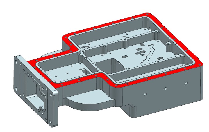
The flatness of the red surface must be free of any deformation. This is quite challenging for 6082-T6 aluminum alloy, as this material grade is prone to deformation during machining. To resolve this issue, our process department has formulated a dedicated machining process in the early stage to improve and control deformation
1.Keep parts for more than 24 hours natural aging after rough machining to release internal stress before finish milling.
2.Adopt multi-step cutting, small cutting depth and high spindle speed for thin-walled parts to reduce machining stress.
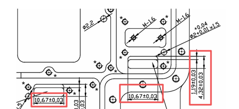
High Threaded Accuracy Requirements of Holes Distance
Communication housing products requires positional accuracy of assembly functional features is required to be ±0.03 mm to ensure flawless assembly.
This poses certain difficulty for aluminum part machining, which can only be achieved with high-precision CNC equipment to meet such accuracy and specification requirements.
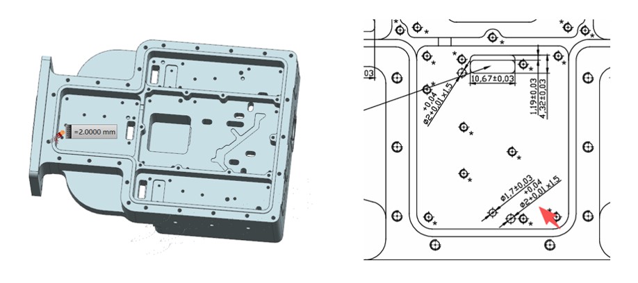
There are numerous 2mm precision locating holes with relatively large depth on the drawing. During machining, it is easy to miss some holes, or produce out-of-tolerance dimensions with oversize bore diameters. In addition, due to the tiny and deep holes, tool breakage frequently occurs in production. We have summarized and learned lessons from the defects and errors found in the first sample trial machining.
Pre-stress Relief Treatment (Prevent Post-machining Deformation)
After roughing the outer profile of the aluminum part, precision hole machining will not be performed immediately. The workpiece will undergo natural aging and low-temperature stress relief treatment to release internal cutting stress. This effectively prevents dimensional and positional tolerance errors caused by micro-deformation of the plate after machining the 100 holes.
Precision hole processing will only start after all surface finishing and cavity roughing are fully completed, ensuring a completely stable datum surface.
- Machining with High-precision CNC Equipment
This process is uniformly performed on high-precision vertical CNC machining centers with a positioning accuracy of ±0.005 mm. It eliminates dimensional errors caused by machine backlash and spindle runout, ensuring consistent hole position accuracy and dimensional uniformity for all 100 holes.
- Step-by-step Machining Process (Rough Drilling → Precision Base Hole Finishing → Precision Reaming)
One-shot drilling forming is prohibited. A three-stage incremental cutting process is adopted to remove material margin minimally, avoiding aluminum extrusion deformation and hole-wall burrs:
Step 1: Rough positioning drilling – Reserve uniform finishing allowance to eliminate drilling deviation and hole position offset.
Step 2: Precision milling for base hole correction – Correct taper, ovality and burrs generated during rough drilling to ensure perfect roundness of the base hole.
Step 3: Precision reaming with dedicated reamer – Final forming of φ2 mm holes, strictly controlling the tolerance within ±0.03 mm, achieving smooth hole walls with no edge collapse.
- Custom Fixture & Clamping Solution
For densely distributed holes, full-plate vacuum adsorption combined with multi-point uniform pressing fixtures is applied. This avoids local micro-deformation caused by single-point clamping, maintains a stable datum during the entire machining process, and ensures unified positioning reference for all 100 holes.
There are numerous 2mm precision locating holes with relatively large depth on the drawing. During machining, it is easy to miss some holes, or produce out-of-tolerance dimensions with oversize bore diameters. In addition, due to the tiny and deep holes, tool breakage frequently occurs in production. We have summarized and learned lessons from the defects and errors found in the first sample trial machining.
Pre-stress Relief Treatment (Prevent Post-machining Deformation)
After roughing the outer profile of the aluminum part, precision hole machining will not be performed immediately. The workpiece will undergo natural aging and low-temperature stress relief treatment to release internal cutting stress. This effectively prevents dimensional and positional tolerance errors caused by micro-deformation of the plate after machining the 100 holes.
Precision hole processing will only start after all surface finishing and cavity roughing are fully completed, ensuring a completely stable datum surface.
- Machining with High-precision CNC Equipment
This process is uniformly performed on high-precision vertical CNC machining centers with a positioning accuracy of ±0.005 mm. It eliminates dimensional errors caused by machine backlash and spindle runout, ensuring consistent hole position accuracy and dimensional uniformity for all 100 holes.
- Step-by-step Machining Process (Rough Drilling → Precision Base Hole Finishing → Precision Reaming)
One-shot drilling forming is prohibited. A three-stage incremental cutting process is adopted to remove material margin minimally, avoiding aluminum extrusion deformation and hole-wall burrs:
Step 1: Rough positioning drilling – Reserve uniform finishing allowance to eliminate drilling deviation and hole position offset.
Step 2: Precision milling for base hole correction – Correct taper, ovality and burrs generated during rough drilling to ensure perfect roundness of the base hole.
Step 3: Precision reaming with dedicated reamer – Final forming of φ2 mm holes, strictly controlling the tolerance within ±0.03 mm, achieving smooth hole walls with no edge collapse.
- Custom Fixture & Clamping Solution
For densely distributed holes, full-plate vacuum adsorption combined with multi-point uniform pressing fixtures is applied. This avoids local micro-deformation caused by single-point clamping, maintains a stable datum during the entire machining process, and ensures unified positioning reference for all 100 holes.
Surface Finishing Analysis
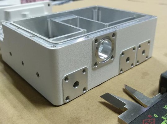
During the post-treatment powder coating process, the white finish frequently presents severe color inconsistency, uneven coating coverage, blurred coating boundaries, and powder overspray onto non-coating areas.
To completely solve the problems of white powder coating color difference, uneven spraying area, unclear coating boundary and powder overspray on non-coating areas, we have formulated standardized improved process measures as follows:
1 Standardize pre-coating pretreatment
Unify the surface degreasing, sandblasting and oxidation treatment standards for aluminum parts. Ensure consistent surface roughness and cleanliness of all workpieces before spraying, eliminate inconsistent powder adhesion caused by uneven base surface conditions, and fundamentally reduce overall color difference.
2 Tooling shielding for precise boundary control
Customize dedicated high-temperature resistant shielding jigs and masking films according to product drawings. Fully cover and shield all non-spraying areas before powder coating. The shielding fixture fits closely with the workpiece profile to ensure sharp, neat and consistent spraying boundaries and completely avoid powder overspray.
3 Standardize spraying process parameters
Unify fixed parameters including spraying distance, gun moving speed, powder output volume and electrostatic voltage. Implement layered and uniform spraying operation, avoid local thick or thin coating, ensure consistent powder thickness and uniform white color tone on all spraying areas.
4 Strict batch color calibration & first-piece confirmation
Perform color calibration with standard color swatches before batch production. Confirm the color, coating uniformity and boundary effect of the first piece, and start mass production only after full verification and approval. Conduct random inspection during production to ensure consistent appearance of all products.
5 Optimize curing process
Unify oven temperature and curing time parameters for white powder coating. Avoid local color deviation and chromatic aberration caused by inconsistent baking temperature and time, ensuring stable and uniform coloring of finished products.