Automotive PA66-GF30 Intake Coolant Connector Housing mold
| Information | |
| Industry | Automotive |
| Product | Coolant Connector Housing |
| Challenges | Deformation, critical dimension requirement |
| Technology | Injection mold |
| Surface Finish | SPI B1 |
| Material | PA66+30GF |
| Quantity | 1*1 |
| Mold size | 450X400X602mm |
Products Introduction
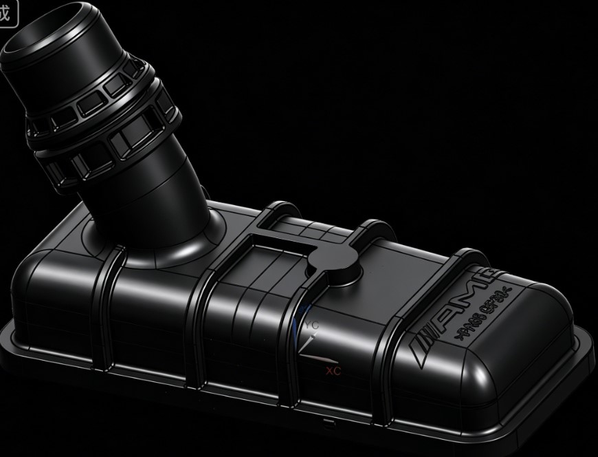
- Angled upper spigot: External serrated anti-slip ribs for interference-fit connection with rubber hoses to prevent pipeline disconnection;
- Rectangular main housing: Multiple circumferential reinforcing ribs on outer wall to boost structural rigidity and minimize sink marks during injection molding; hollow internal cavity for fluid circulation;
- Bottom mounting flange: Perimeter sealing lip for bolted assembly onto engine or cooling module mating face, with pre-designed sealing groove on the fitting surface.
Application
It is a plastic fitting housing for automotive engine cooling or intake system, serving as flow channel for coolant or blow-by gas, commonly applied in turbocharger liquid cooling, EGR exhaust gas loop or intake manifold piping assemblies.
DFM Analysis
Mold design
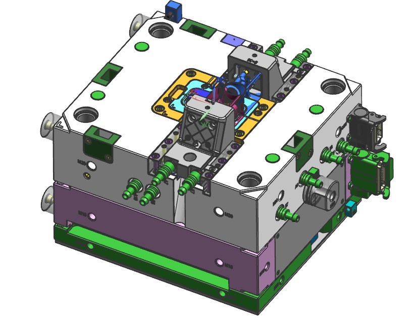
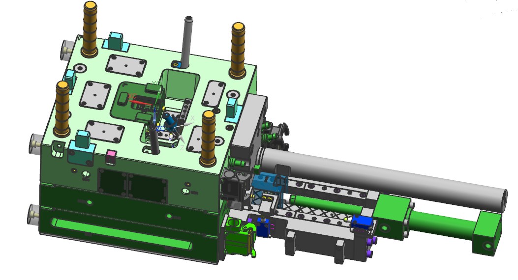
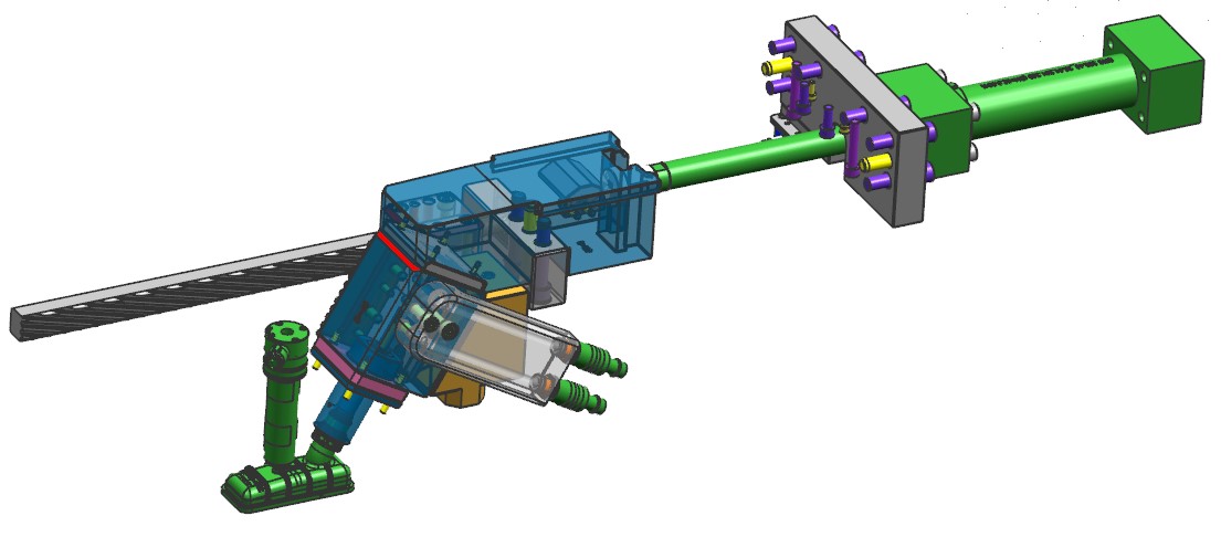
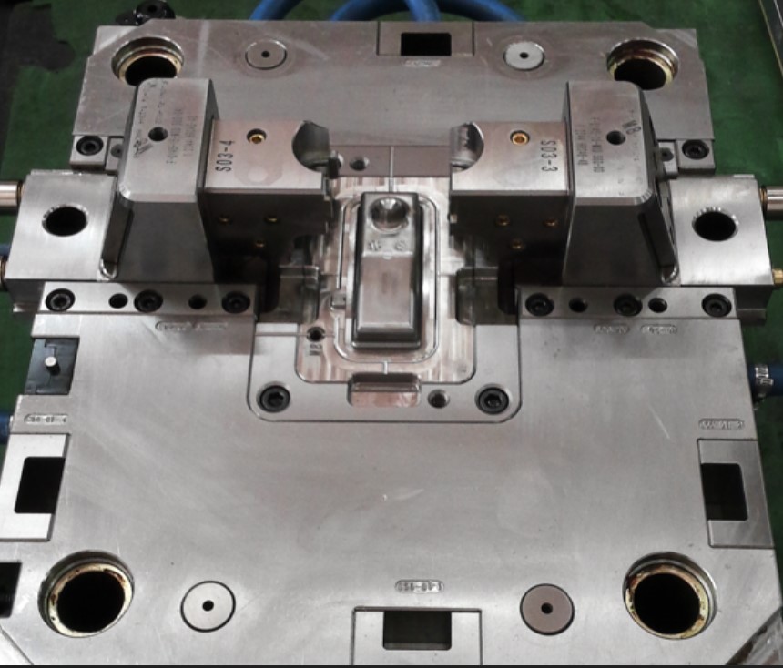
Mold making and Fitting
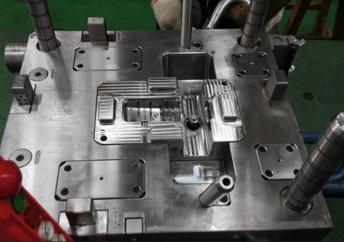
Key point on the part
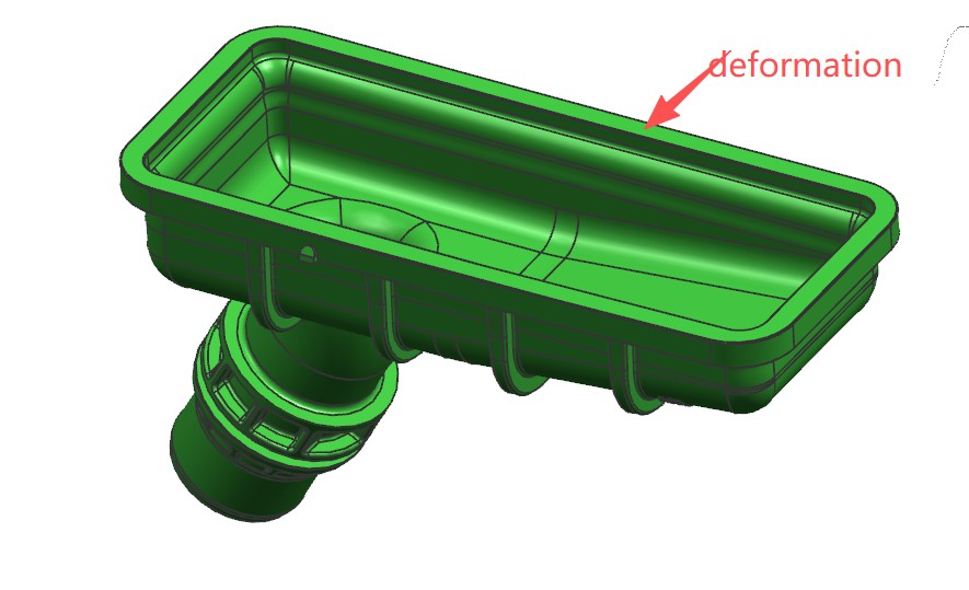
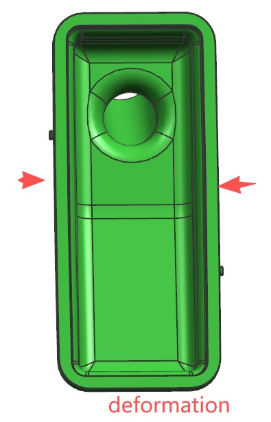
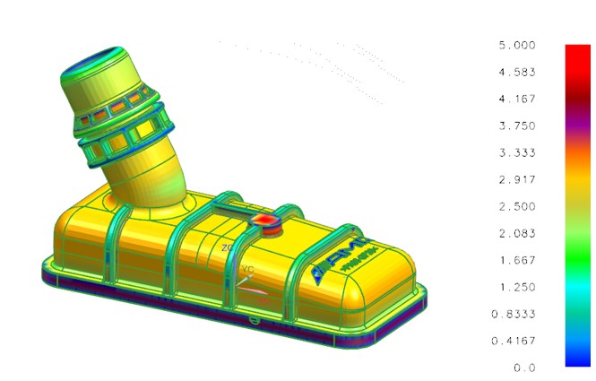
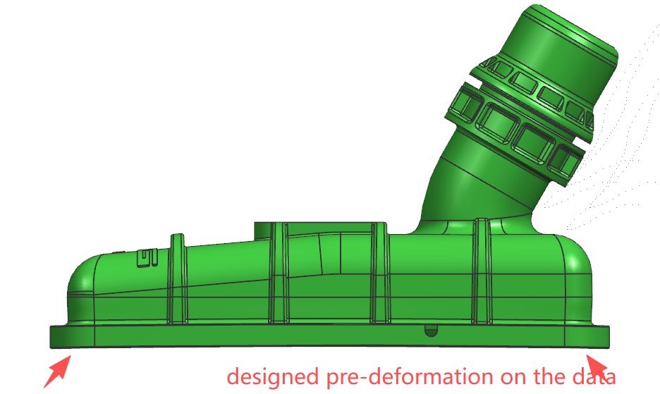
The surface indicated by the arrow on the component is prone to dimensional deformation, which constitutes a critical and highly challenging difficulty in mold fabrication. Therefore, precise mold flow analysis reports are of vital importance. During the upfront product design phase, deformation allowance must be pre-calculated, namely implementing pre-deformation compensation on the mold core/cavity. Even after trial molding, the flatness of molding parts often fails to meet tolerance specifications, hence the mold construction needs to reserve sufficient design margin for post-trial revision.
After rounds of internal engineering reviews, our technical team formulated the following solution:
- Conduct thorough mold flow analysis to finalize the optimal gate location that minimizes part warpage; based on the simulated deformation data, apply targeted pre-deformation offset on the product geometry in advance.
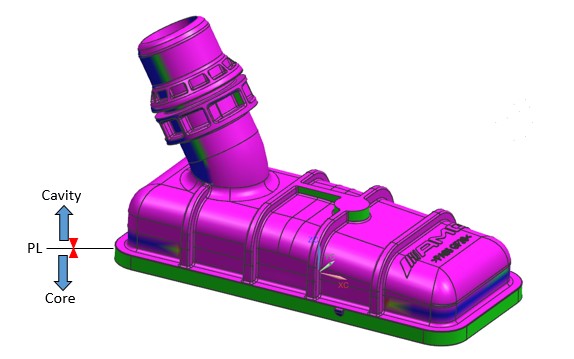
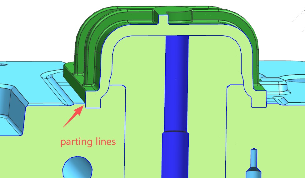
- Avoid placing the parting line and split surface at the rounded-corner(R) positions in mold layout design, reserving adequate steel stock for future mold modification.
- For the core inserts, we adopt pre-hardened S50C for initial trial molding. After trial testing, the finished parts are inspected by CMM (Coordinate Measuring Machine) to measure actual warpage values. Once real deformation data is confirmed, the core inserts will be re-machined with 1.2344 steel hardened to HRC48~52. Welding is prohibited for this mold.
Despite higher manufacturing costs, this strict process is mandatory to guarantee superior mold quality, as we pursue high standards for every single mold we manufacture.
Summary
The part may seem simple, but strict requirements for appearance and assembly demand extremely high mold machining precision. We adopt imported DMG CNC machines, Sodick EDM and wire cutters for production, keeping machining tolerance within 0.02 mm.
All components undergo full inspection of CMM after processing to eliminate defects at the early stage and minimize issues during subsequent mold trials. The customer attended the trial run and highly praised our solution of designed the pre-deformation to resolve product deformation. Despite the higher costs, the final trial results fully satisfied the client.