Tool box mold
| Information | |
| Industry | Toolbox |
| Product | Tool box mold |
| Challenges | Deformation, critical dimension requirement |
| Technology | Injection mold |
| Surface Finish | Cavity: texture/Core:SPI-SPE B-3 |
| Material | ABS |
| Quantity | 1*1 |
| Mold size | 846X846X807 mm |
Products Introduction
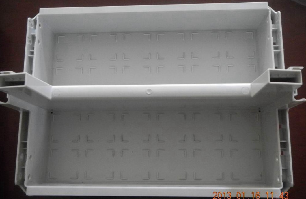
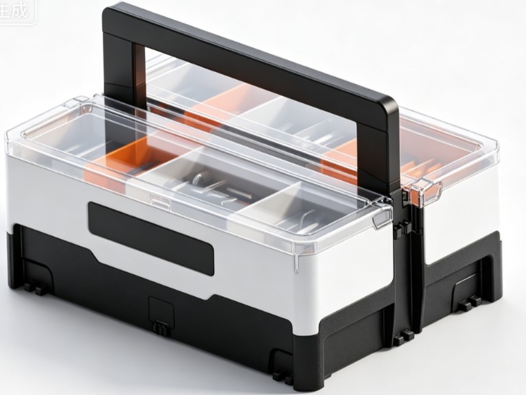
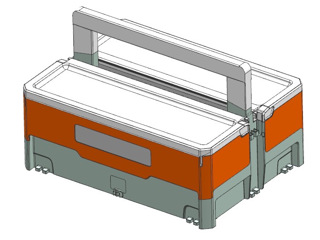
Compartmentalized Storage: Dual independent inner cavities separate spanners, screws, electronic components and small hardware parts to avoid messy arrangement.
Portable Carrying: Integrally molded top handle enables easy transportation for field maintenance, auto repair and electrical work.
Protective Storage: Rigid plastic housing delivers anti-collision, dustproof and moisture-proof performance to safeguard precision tools and lithium cell components from impact damage.
Stackable Interlocking Design: Central snap-fit structure allows multiple toolboxes to clip together for neat warehouse stacking.
Additional Design Advantages
Transparent top trim ring enables visual inspection of stored items without opening the lid for quick part retrieval.
Bottom positioning snaps lock the box onto workbenches or vehicle slots to prevent sliding during operation.
Three-piece split casing: colored mid-shell improves surface appearance, black base boosts structural rigidity, transparent top frame serves as dust-proof sealing edge.
- Key Challenges for Injection Molds
The product requires three separate injection molds: black base, colored middle frame, transparent top rim.
- Molding Difficulties – Black Bottom Base
Dense bottom snap posts: Numerous tiny cylindrical positioning pins require abundant small mold inserts made of pre-hardened 1.2344 tool steel to avoid insert breakage and product sticking.
Large flat panel warpage risk: Thin-wall large-area base suffers uneven shrinkage with PP/ABS materials; conformal cooling channels are machined on mold core plus reinforcing ribs on product to minimize thermal deformation and temperature difference.
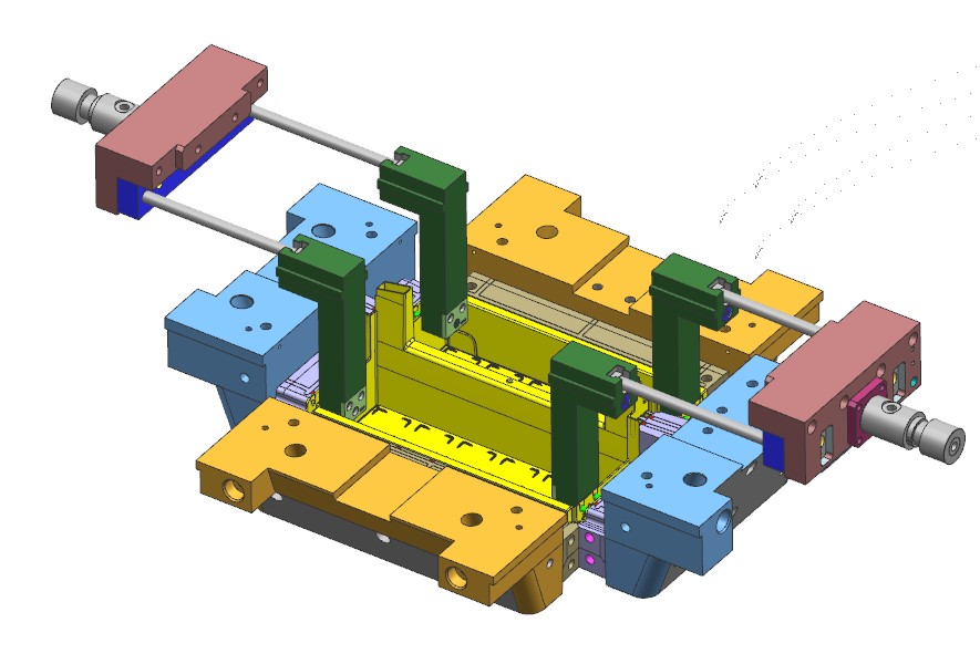
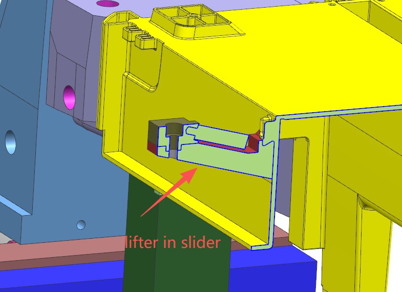
Recessed side assembly slots: Undercut side features need slide core side pulling structure with tight clearance control to eliminate flash.
- Molding Difficulties – Colored Middle Shell
Long curved cosmetic surface: No weld line or sink mark allowed on visible exterior; submarine side gating is adopted to keep gate vestige away from appearance area.
Precision central interlock snaps: Split independent inserts for mating clips with dimensional tolerance ±0.04mm to guarantee proper assembly tightness without excessive looseness or jamming.
- Molding Difficulties – Transparent PC Top Rim
Zero-defect cosmetic requirement for transparent PC: PC resin is prone to silver streaks, bubbles and sink marks; high-gloss mirror polishing on mold plus full-round runner and optimized venting system are mandatory.
Thin-walled annular distortion: Uneven cooling along long thin ring causes dimensional warp; full surrounding conformal cooling and staged packing pressure are applied with pre-set shrinkage allowance.
Precision fit with middle frame: Strict dimensional tolerance for inner & outer diameter to ensure seamless insertion onto colored housing.
- Integral Carry Handle Molding Obstacles
Long-span cantilever shrinkage: Downward sagging from plastic shrinkage is compensated by reverse arch pre-deformation design on mold core.
Uneven wall thickness at handle junction: Thick-thin transition easily triggers sink dents; enlarged transitional fillets and beryllium copper inserts for local accelerated cooling are implemented.
- Assembly Dimensional Control
Three separately molded components rely on snap assembly without adhesive; closed-loop dimensional tolerance chain across all three molds is required to prevent uneven gaps or misalignment during final fitting.
DFM Analysis
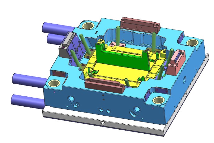
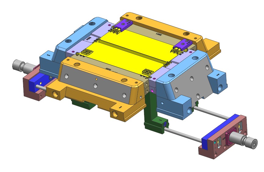
Mold design
Mold making and Fitting
Key point on the part
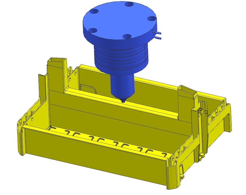
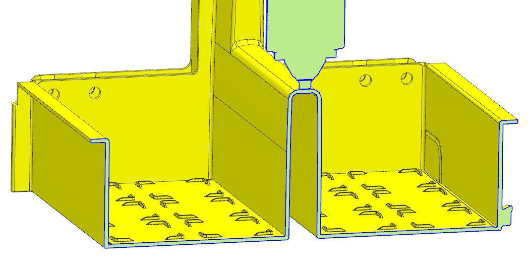
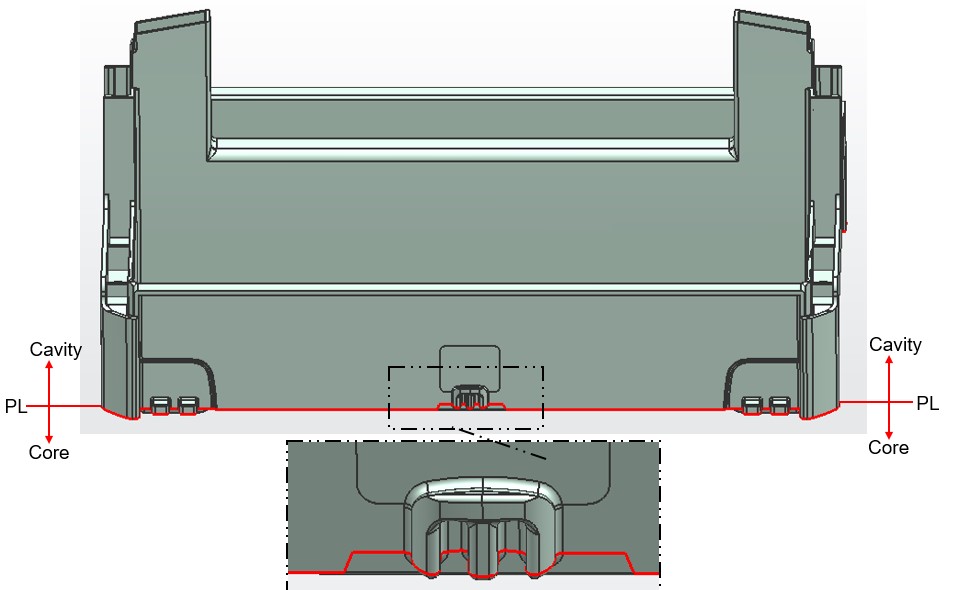
Gate is setting at the middle section of the product. The melt tends to shift during injection molding. Due to the extremely tall insert at the central position, the insert is prone to deflection under injection pressure, resulting in inconsistent wall thickness of molded parts and further downgrading the structural strength of finished products.
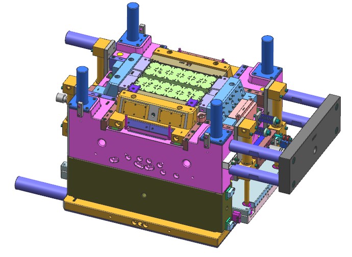
Therefore, the mold insert requires robust fastening with zero machining tolerance deviation, and the machining precision shall be strictly controlled within 0.03 mm.
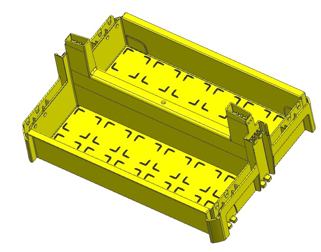
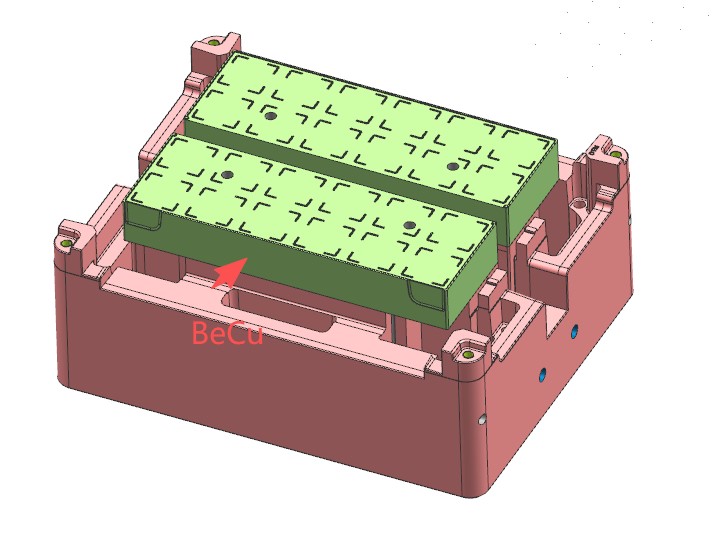
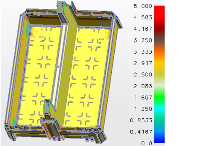
The nominal wall thickness of the product is 2.5 mm with a tall overall height. Hence, the mold is equipped with high-efficiency cooling circuits to minimize part warpage and shorten molding cycle time.
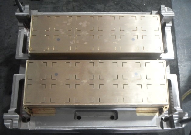
Beryllium copper inserts are applied at these two critical regions for enhanced heat dissipation. Meanwhile, we optimized the cooling channel layout: the distance between cooling lines and part cavity is strictly controlled within 12~15 mm, and the runner length of cooling water is shortened to realize faster mold cooling efficiency.
Summary
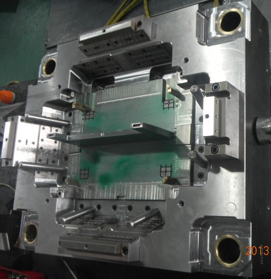
The part may seem simple, but strict requirements for appearance and assembly demand extremely high mold machining precision. We adopt imported DMG CNC machines, Sodick EDM and wire cutters for production, keeping machining tolerance within 0.02 mm.
All components undergo full inspection via CMM after processing to eliminate defects at the early stage and minimize issues during subsequent mold trials. The customer attended the trial run and highly praised our solution of BeCu cooling inserts to resolve product deformation. Despite the higher costs, the final trial results fully satisfied the client.