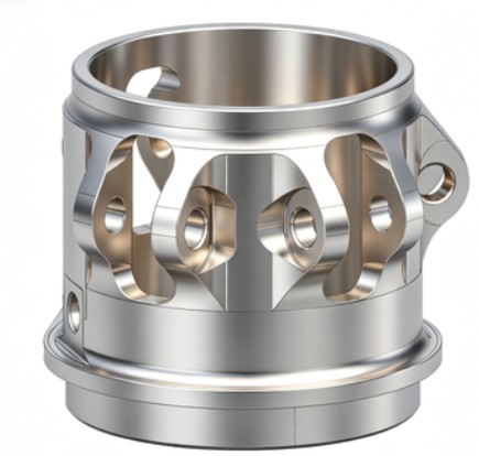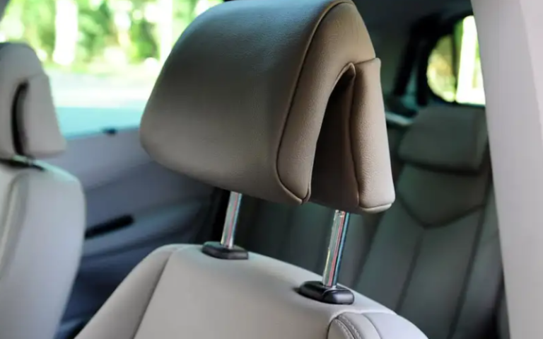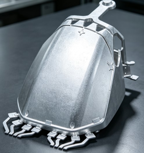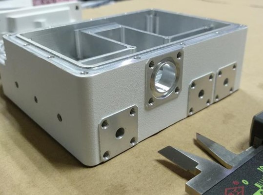
Automotvie console cup holder mold
| Information | |
| Industry | Automotive |
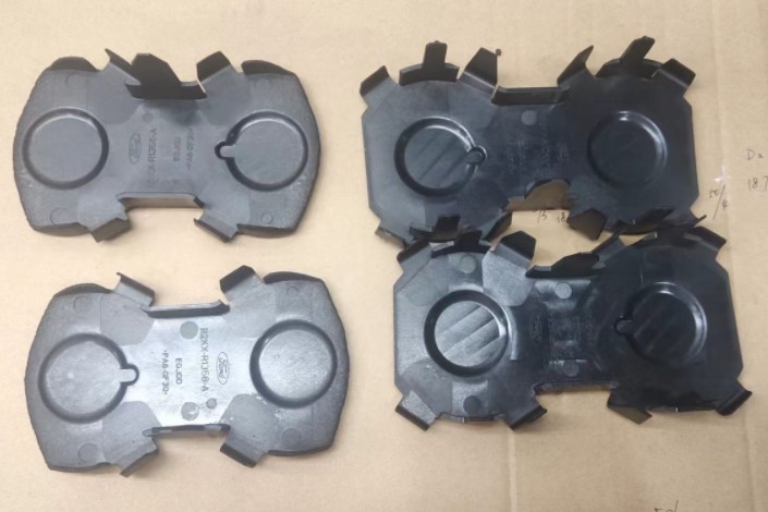
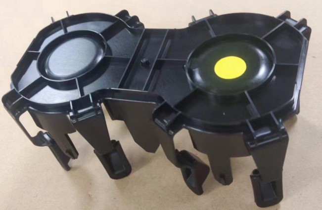
| Product | Cup Holder Finger |
| Challenges | A lots of undercuts on the part |
| Technology | Injection mold |
| Surface Finish | SPI B1 |
| Material | PA6-GF30 |
| Quantity | 1*2 |
| Mold size | 1460*730*833mm |
Products Introduction
- Structural Features
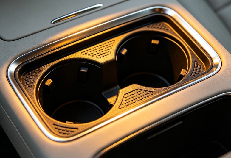
Integrated dual barrel structure with thin wall, side clips, limit grooves, reinforcing ribs and undercuts. It serves as both appearance and functional assembly part, mainly used for center console and car door.
- Application Requirements
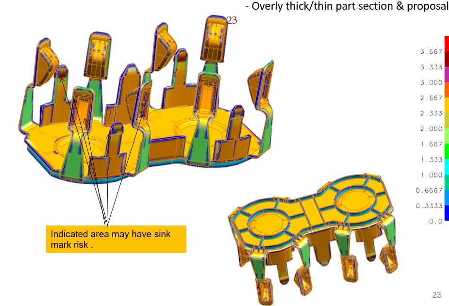
No sink marks, warpage or ejection marks. No obvious gate marks or weld lines on surface. High dimensional accuracy for assembly and good durability for repeated use.
tolerance enables easy installation and removal.
Key Points for Injection Mold Design
2.1 Overall Layout & Cavity Arrangement
- Mass production adopts symmetric layout: 1-cavity for 2 pieces / 1-cavity for 4 pieces to ensure balanced material feeding and cooling.
- Use two-plate mold or hot-runner two-plate mold. Hot runner is preferred for high-volume production to eliminate sprue waste.
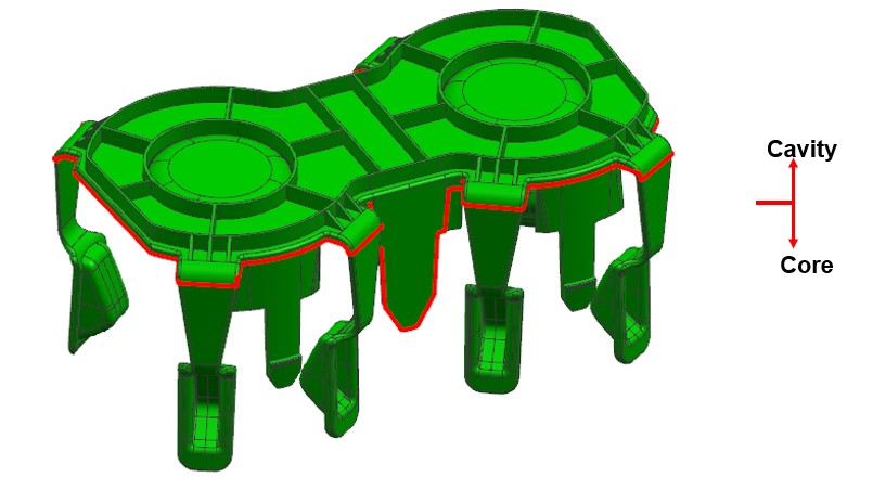
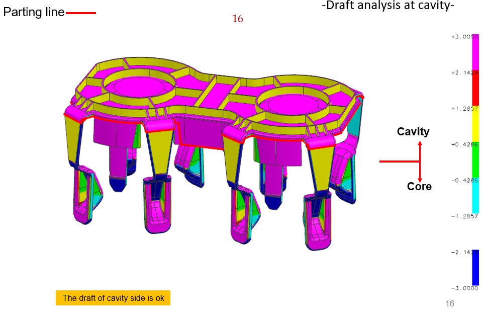
- Main parting line follows the maximum outer contour of the product to avoid visible surfaces.
2.2 Draft Angle
- Inner & outer walls of cup barrels: 1° ~ 2°. Larger draft angle for deep barrels to prevent surface scratch during ejection.
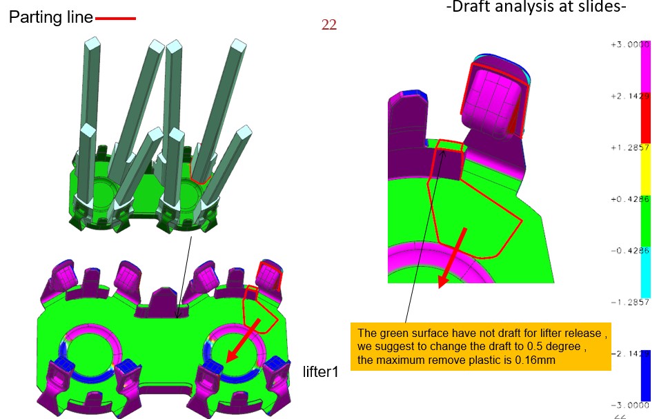
- Reinforcing ribs and clips: Draft angle ≥ 0.5°.
2.3 Undercut & Side Core Pulling (Core Structure)
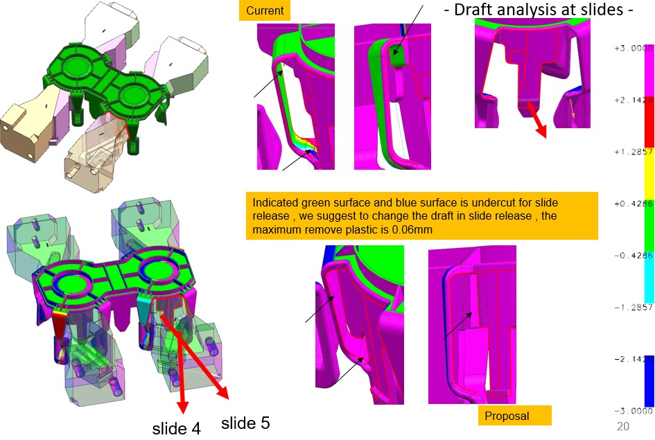
- Lifters are adopted for side clips and limit bosses/grooves with undercuts. Use hydraulic cylinder core pulling for large undercut travel.
- Fit wear plates and positioning guides on lifters to avoid sticking and displacement during long-term operation.
- Check motion interference and ensure tight mold clamping to prevent flash.
2.4 Gating System
- Hot-runner pin gate is recommended for appearance parts, located at inner bottom (non-visible area).
- Side gate or fan gate for small & medium batch production. Gates shall keep away from load-bearing clips and assembly surfaces.
- Polish runners thoroughly and shorten flow length to reduce weld lines, which must not be placed on load-bearing or assembly areas.
2.5 Cooling System (Anti-Warping Focus)
- Adopt surrounding cooling circuits separately for cavities and cores. Distance between water line and mold surface: 10~15 mm.
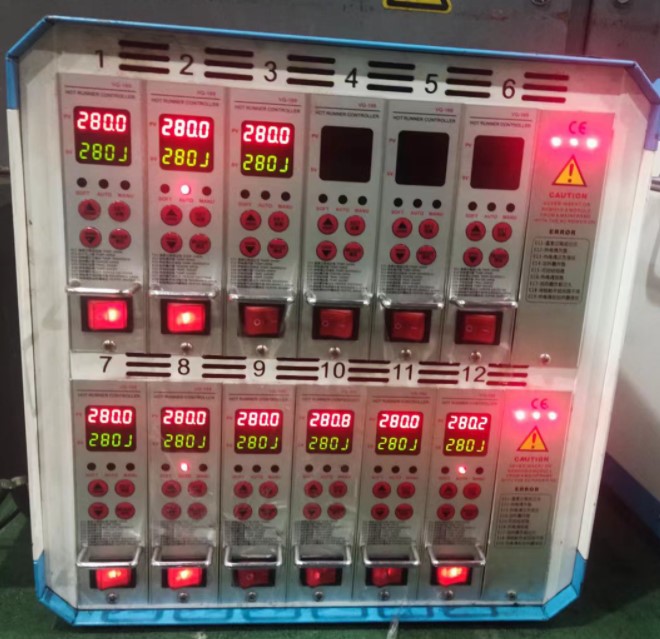
- Mold temperature: 60~80℃. Even cooling layout reduces temperature difference, warpage and dimensional deviation.
- Add independent cooling circuits for lifters and slides to avoid local heat accumulation.
2.6 Ejection System
- Combine ejector sleeves and ring ejector pins for main barrel parts to realize uniform ejection and avoid ejection marks, dents and deformation.
- Add flat ejector pins at ribs and edges for synchronous ejection.
- Adopt multi-speed ejection for smooth demolding and surface protection.
2.7 Venting Design
- Set vent slots at barrel bottoms, rib intersections and weld line areas. Slot depth: 0.01~0.02 mm.
- Sufficient venting prevents burning, short shot and air bubbles (PA66 is prone to thermal decomposition at high temperature). Keep identical venting specification for all cavities.
2.8 Mold Steel & Surface Treatment (Automotive Standard)
- Cavity & core: 718H, P20 for regular mass production; S136,1.2344ESR for high-lifetime & high-gloss appearance parts.
- High wear-resistant steel for moving components (lifters, guide pins, slides) to meet long production cycle.
- High-gloss polishing for appearance surfaces and fine finishing for assembly surfaces, free of burrs and scratches.
2.9 Dimensional Tolerance
- Tolerance of mating surfaces: within ±0.05 mm.
- Control clearance of parting lines and core-pulling parts strictly to prevent flash.
2.10 Deformation Control
- Conduct accurate cavity compensation based on material shrinkage, considering shrinkage difference between flow direction and cross flow direction.
- Ensure uniform product wall thickness and sufficient mold rigidity to avoid permanent deformation during long-term production.
DFM Analysis
Mold design
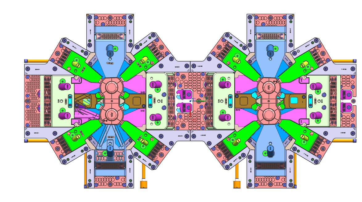
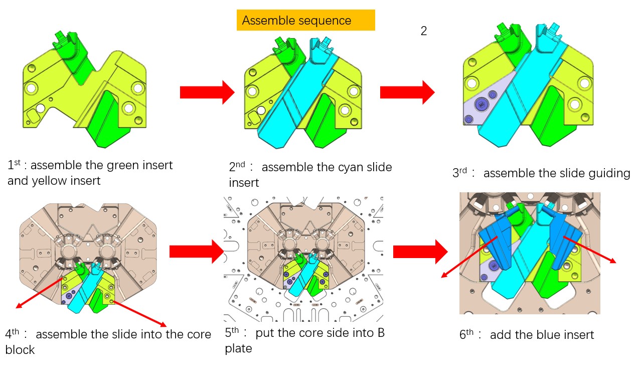
Mold making and Fitting
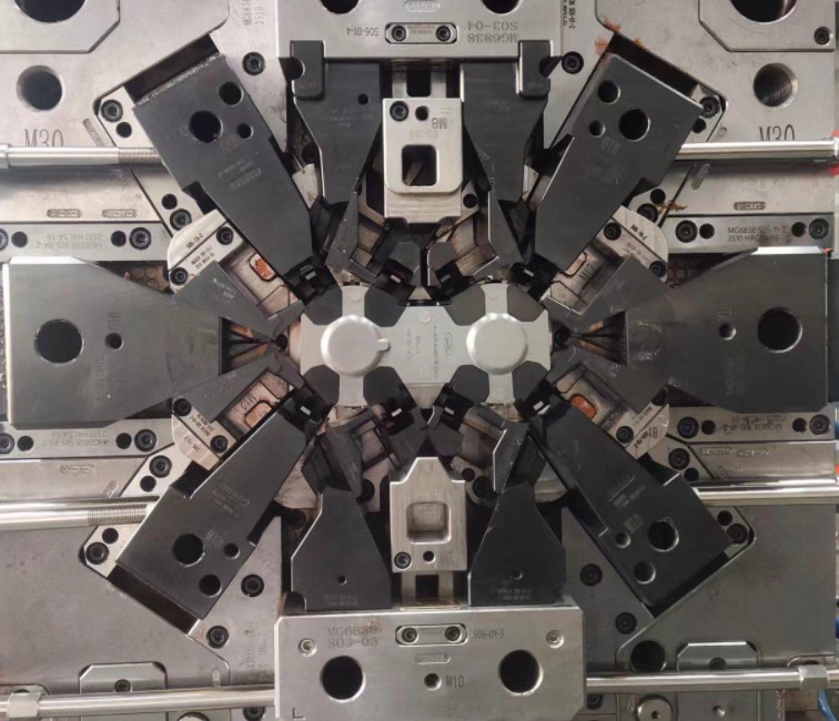
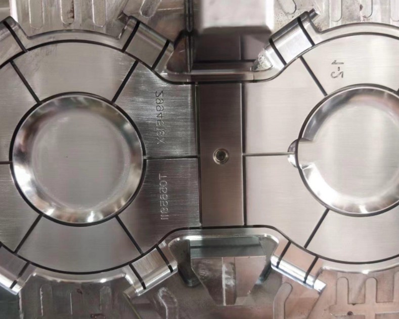
Mold Trial and Testing
Filling part
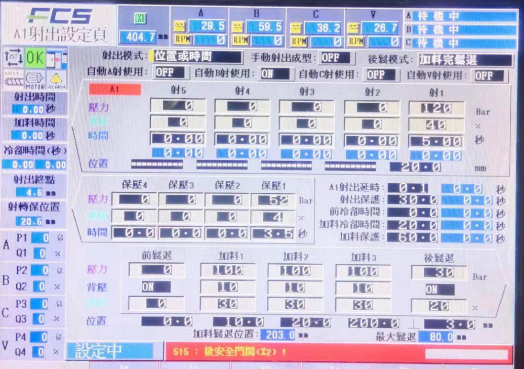
Parameters
Summary
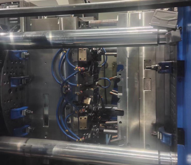
This mold features numerous secondary slides. Given that PA6+30GF material requires a high mold temperature, slide burn marks easily occur during production, which demands extremely high fitting precision for the mold.
We adopted DMG CNC machines, wire EDM and high-precision grinders for all machining processes to guarantee top-tier component quality. The mold was assembled with zero hand-fitting. Additionally, DLC coating was applied to all slides to enhance surface wear resistance and prevent burn marks caused by thermal expansion at high temperatures.
From design drawing completion to the first trial run, the whole process took 8 weeks. The trial result was excellent and has won high recognition from the client.